Datapath and Instruction Fetching
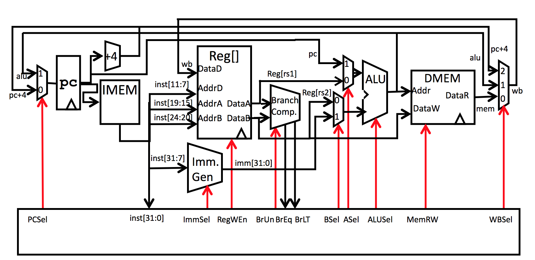
1.2 Datapath
The functionality of a CPU is basically a progress calling, computing, and storing data based on given instructions. You can think of your cabinets and you are basically trying to deal with your clothes. If you want to wash your white shirt (this instruction is from a note you picked from another cabinet), what should you do? You should probably first find the white shirt in your cabinet, then pick it out, put it into the washing machine. Then, after some minutes, pick them out and put the clean shirt somewhere in the cabinet again. Then, say if you want to store some washing powders for further usage, you may put that into the cabinet (find a proper spot) where you got the notes for the instructions.
The cloth here is just like the data, the cabinet where you pick the instructions and store the washing powder is the memory, and the cabinets where you get the cloths from are the registers, and the washing machine is like your ALU (performing arithmetic operations as required, continuing the example, this "operation" can also be drying or rinsing).
We will first development a single-cycle system in Stage-1. In Stage-2, we will implement Pipelining to increasing the performance of our CPU.
1.2.1 Difference between Registers and Memory
Register: Holds the data that CPU is currently processing; Memory: Holds program instructions and data that the program requires for execution.
Thus, as "temperate" access storage of data, we can increase the speed of our CPU by increasing the number of bits in the CPU or just increasing the physical number of registers.
2. Instruction Fetching Structure
The instruction fetching structure includes the process we extracting instruction from our memory, and how our CPU will return an address to call for next instruction.
2.1 Instructions
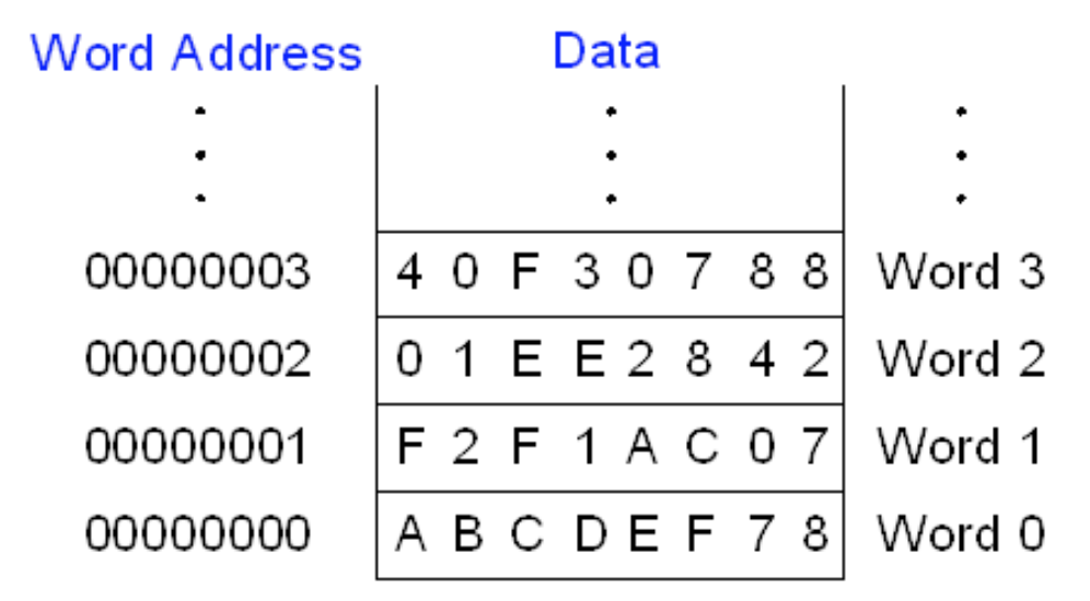
In this project, we use a word-addressable memory system
Word-Addressable: In computer architecture, a word is an order set of bytes or bits that is the normal unit in which information may be stored, transmitted, or operated on within a given computer. If a computer's memory is word-addressable, then it means each word in memory is assigned its own memory address. It can be understood that, for example, if each instruction has a certain, equal length of bits, let's say 4 bits, then, in order to keep going extracting instructions from our memory, we need to set our pointers 4 bits ahead every time. However, if the memory is word-addressed (note that real-word computers are all bit-addressed, mostly word-addressed systems are just ideal or convenient understanding of ideas), then each instruction is stored in one address and we just pass by one address each time.
2.2 PC
Try to first understand the usage and development of PC by its name (program counter). This the a separate register keeping track of where have we been and where we should go as a pointer to the memory where we store our instructions. Usually, for normal instructions, we may just adding PC+4 to get the next address for our next instruction. However, since our memory is word-addressed, we need to do a further operation to our PC to get the correct address our CPU fetch to for the next instruction. In this project, we use fetch_addr to indicate the address of our instruction.
2.3 Building Instruction Fetching System
Note that we'll be using 8 32-bit registers (except for x0) in this CPU.
First, we already know basically how a CPU works. And there are several inputs and outputs we need to take into consideration. The inputs for CPU is the registers and the Instruction, while the output is the fetch_addr for the next instruction.
Now let's get started!
2.3.1 Main Panel
We first define some registers that we'll use for the CPU. 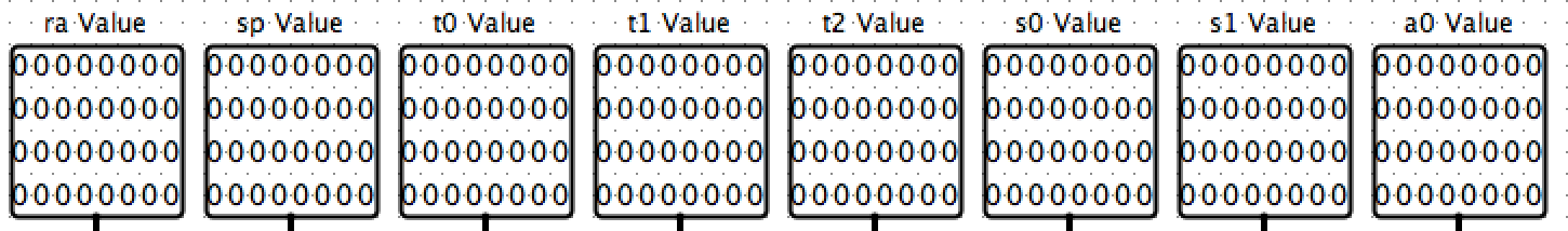
Then, we connect them to our CPU, which takes in Instruction and outputs fetch_addr 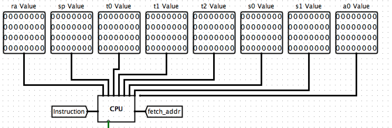
We need to have a memory storing the instructions so that our CPU can load instructions from, right? And we need to let it be able to get the instruction given the address. > Note we are probing the Instruction and fetch_addr just for convenience checking and debugging. 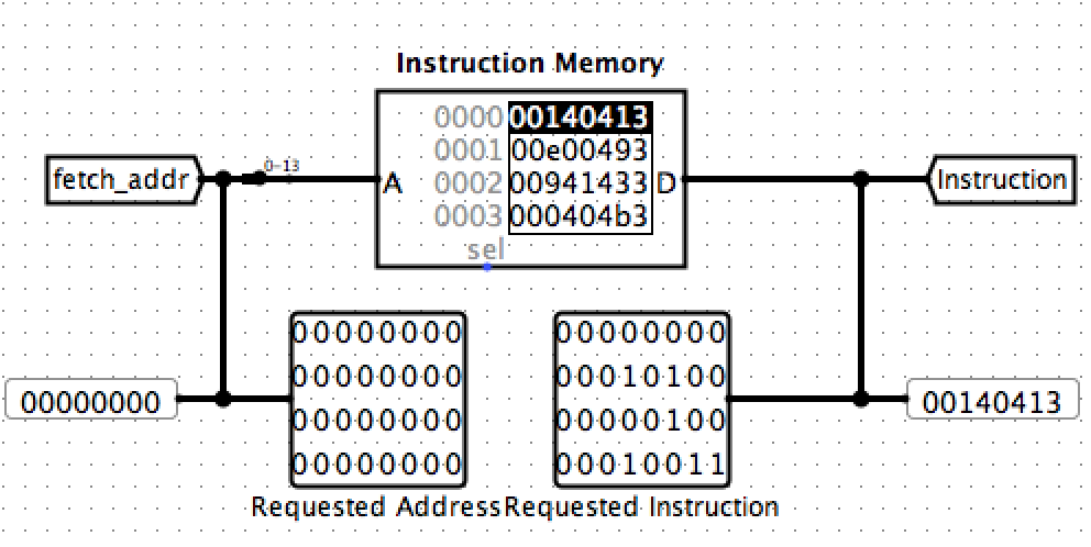
Finally, we can also define a Time Step to track how many instructions have we loaded. This is optional and we can a light halt just for noticing. 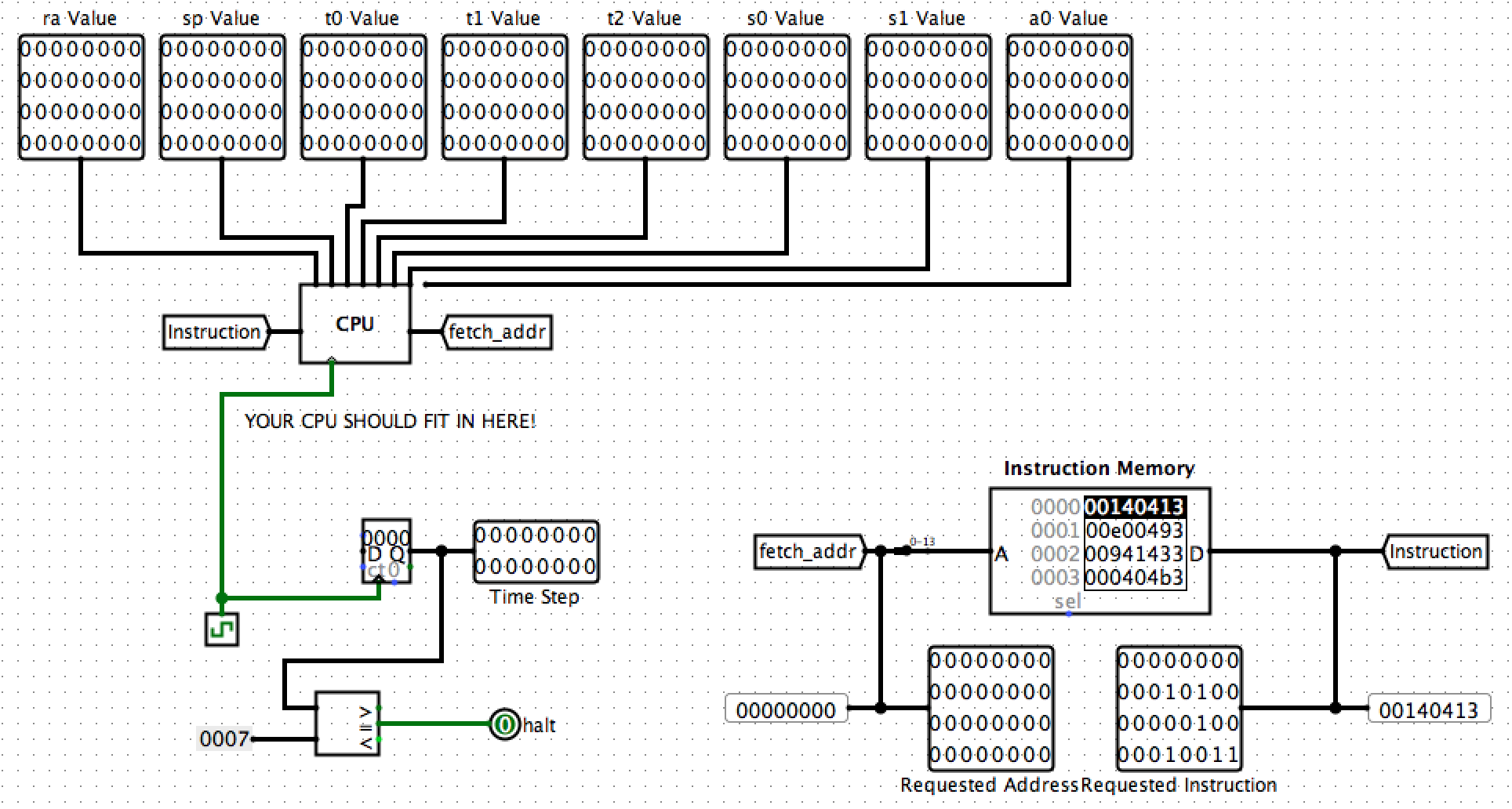
Then let's go inside our CPU. We just focus on PC part. Re-view the card of instructions we will be able to implement by this CPU, see what is related to our PC. There are many special operations we need to deal with the data passing into PC, for example, jal and jalr.
This means that we cannot simply do PC+4 every time. See the PC part on our Datapath, we will make an selection between traditionally doing PC+4 or using the calculated new address (since the calculations were done by the ALU, we just name the output of ALU as ALU), which is ALU. The selection index is named PCSel which is from the control panel. We will deal with the PCSel and the controllers later.
2.4 PC in CPU
2.4.1 Input/ Output
First we can note the input/output and the clock signal in our CPU circuit. 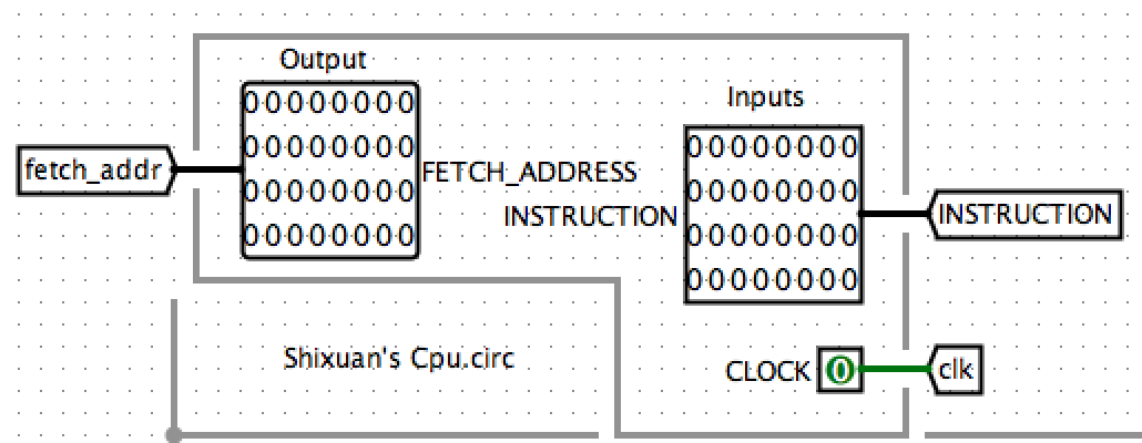
Then let's define the input/output (value-setting and value-reading) of PC. 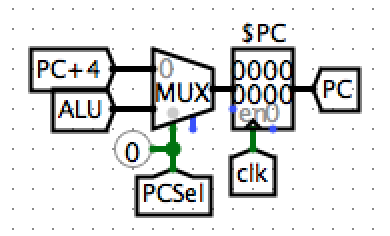 where the
 PC+4 is defined as 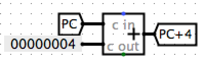
Note that we implemented an Multiplexer in our PC unit, which is denoted as MUX in the circuit. Just in case your confusion, here is more information about Multiplexer
Now, did you notice what we are still missing? Yes, the fetch_addr! Since we already know that we have a word-addressed memory and the instructions go by 4 bits, the lowest two bits of the instruction address must be 0 (minimum for a multiple of 4 is 0b0100). Thus we just right-shift our PC (basically it is the same as we divide it by 4) by 2 bits and get the fetch_addr. 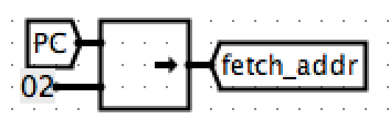
2.4.2 Controller
Now we turn back to the PCSel, the controller which decides which value to be assigned to our next PC. How should we make the selection? Let's first take a look of our Instructions Sheet: 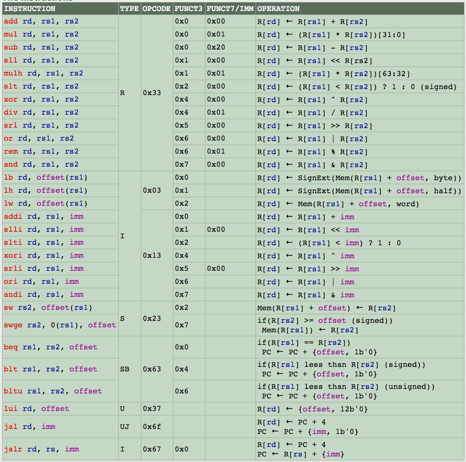
From the sheet we notice that the value of our next PC is irregular only when there's a branch or a jump. Let's first focus on the branches. The PC value is affected only if branches' conditions are met. Thus we make a or Gate to select from our conditions and set each argument a and Gate which we say the condition is met only when there's a branch instructions and it's condition is met. For example, here's what we do with the branch instruction beq: 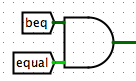
Then let's see the jumps, which refers to jal and jalr. Since it's obvious that we take the PC value from ALU anyways when there's a jump, we just add them to our selections. Thus, our final selection has structure of: 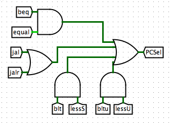
Note that we have the condition testers equal, lessS, and lessU. They are defined simply comparing the values of our R1 and R2. The structures are below: 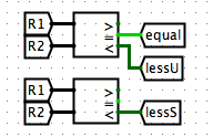
Now we're done for the instruction fetching part in our CPU. In Part 3 we'll be talking about Decoding and ALU selection where we separate the instructions to get information for them.