Memory Management and Write Back systems
6. RAM and Write-Back
A Random-access memory (RAM) is a form of computer data storage that stores data and machine code currently being used.
Remember Bob's story in Part 4? The RAM is just like the cabinet where Bob store the data in his first & second bag and then re-load the data.
6.1 RAM Design
Now let's think about the parameters required to realize this process. First, to store some data into the memory, we first need an address in memory to know where we are storing the data. Then we need to provide the data. And a signal saying if we want the data to be stored or not since the difference between the instructions. And we just output the data in that address for further usage.
Since this part is quite obvious to understand, I just show my structure. 
6.2 RAM in CPU
Since we've successfully designed our RAM unit, the only problem is how can we connect our RAM in our CPU system. Let's first take a look our Instruction Sheet: 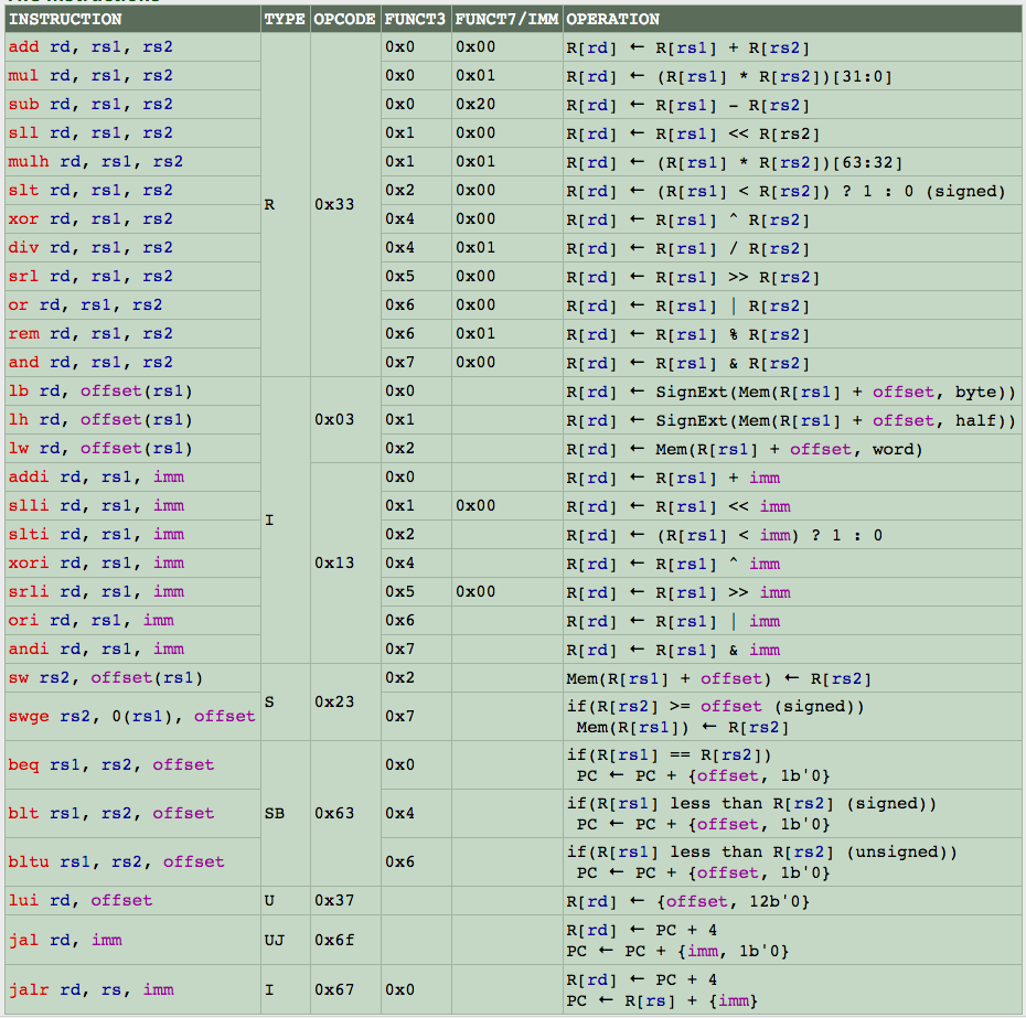
6.2.1 Controller
We can see that we are only writing in our memory when there's a save instruction which refers to sw and swge(when condition is met). Thus, we can first define our controller for the conditions: 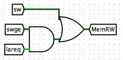
in which our condition for swge is defined as 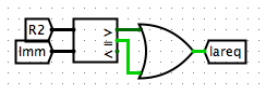
6.2.2 Inputs/ Outputs
We need to pass in the address and the data. From the Instruction Sheet we notice that the address can be generated as the output of ALU. Thus we set the address input to be ALU. And we can see that the data to write in are all from R2, thus we set that to be our input for data. Lastly, we name our output mem_read since this represents the data read from the memory with given address.
6.3 Write Back Selection
Remember the WB(write back) we mentioned in Part 4 in RegFile? The write back data determines what we write into the registers. Depending on different instructions, this can be really different. Let's look back into the Instruction Sheet. For example, the load functions loads data from memory into the registers, thus we are using data loaded from memory. The jump instructions including Utype and UJtype passes increased PC into the registers and thus we write back information about PC. For others such as Rtype, Utype and Itype-Other, we may just pass the result from ALU. Thus we are building a selection method. We've been building the selection methods many times with Multiplexer. We first define the selection method: 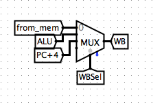
And then we define the selection controller: 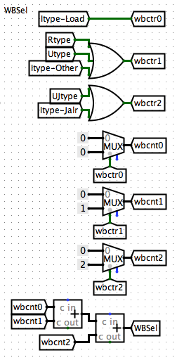
You may noticed that we did not use the same data as the input data for the data read from the memory (from_mem rather than mem_read). This is because, as you may noticed, we have different types of loading instructions (lw, lh, lb), each corresponds to different loading options. Thus we build a selection and loading method for the data loaded from memory. The intuition here is that we need to implement the data loading for all three types of loading and return the correct one based on our selection method noticing which type of instruction we are using.
Notice that lw loads 8 bits which is just the original data, lh loads half word which is 4 bits and lb loads 2 bits. Thus we need special data load for lh and lb: 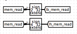
Then we develop a selection method: 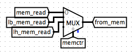
And define the selection controller: 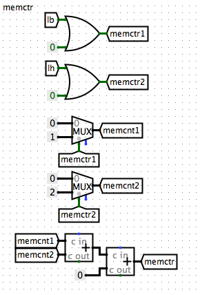
6.4 Single-Cycle CPU!
Congrats! We've successfully developed a fully functional Single-Cycle CPU! Let's see what we've achieved! Remember the following structure? Do some review and try to think of our intuitions for each step revealing the CPU. 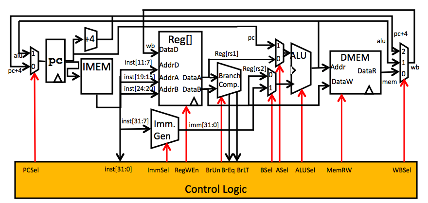
In Part 7 we'll be talking about PipeLining and make our final Two-Cycle CPU!