ALU Design and Input Selection
5. ALU System
An Arithmetic Logic Unit (ALU) is a combinational digital electronic circuit that performs arithmetic and bitwise operations on integer binary numbers.
We will talk about the designing of the ALU system and the input control of ALU in the CPU system. Note that in this part we might use some result achieved from Part 3 (ALUSel). Reviewing Part 3 is recommended.
5.1 ALU Design
As we've talked about in Part 3, our ALU will take in two inputs (remember Bob's story in Part 4?) and do certain operations following instructions given by ALUSel. We perform an Multiplexer to select the proper arithmetic unit in ALU to be performed. Since in Part 3 we've assigned a certain indexing of arithmetic units, which is shown below, we will design out ALU system based on that.
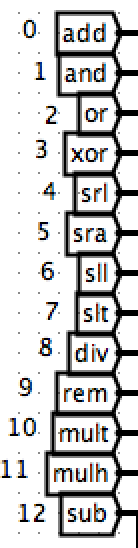
Note that we have totally 13 arithmetic units to be performed > add/ and/ or/ xor/ srl/ sra/ sll/ slt/ div/ rem/ mult/ mulh/ sub
5.1.1 ALU Output
Since we already know the output format, let's just put it out: 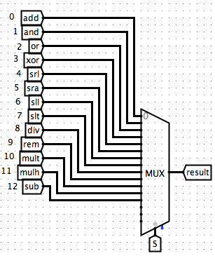
5.1.2 General Output
And indeed I also added a signal of equal which is 1 if two branches are equal (also I didn't really use it in the project, it does look pretty with this little "light"). The general output is as following: 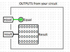
5.1.3 ALU Inputs
Also we'd better define the inputs at the beginning as well: 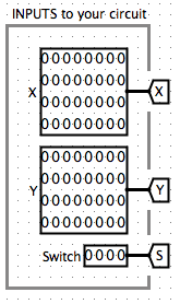
5.1.4 Arithmetic Units
Then the last part is just adding arithmetic units for each operation we want. This part is actually easy since we can find really direct Gates or Arithmetic units from the tools in Logisim. So I'll just post here my results: 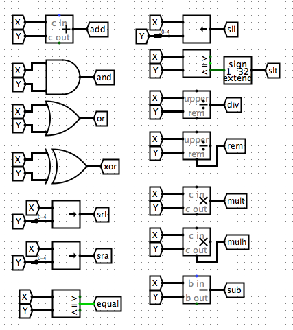
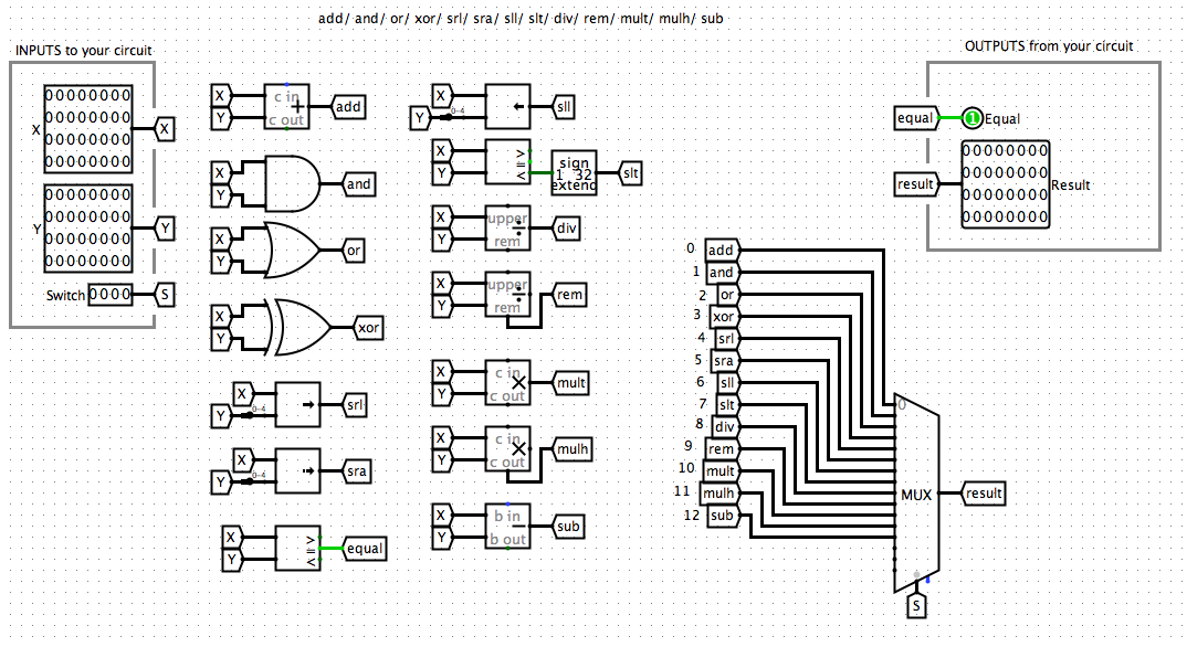
5.1.5 Overview
Now we've finished the designing for the ALU. And here is an overview of the whole picture:
5.2 ALU in CPU
Let's first see what we've achieve for ALU in spec of the CPU system: 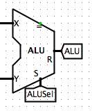
Obviously the only problem now is how we should deal with the inputs. Let's first review the Datapath in a Single-Cycle CPU: 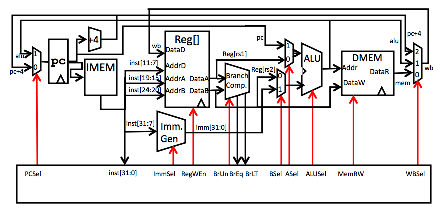
And the instructions sheet: 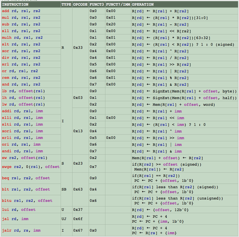
5.2.1 Input of ALU [Input X]
Let's first focus on the first input of the ALU, which we denoted as Input X in our circuit. From the Datapath we can see that there are basically two options we need to choose value from. The first one is PC and the second one is Reg[rs1], which corresponds to R1 in our circuit. But when do choose from each of these? Since it is obvious that we'll need to use a Multiplexer here again, the question can also be addressed as "What is the selection controller (ASel) for input 1?"
5.2.1.1 Intuitions for Input X
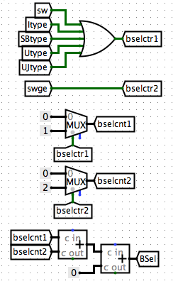
From the instruction sheet we notice that when the instruction is an SBtype or UJtype, we implement ALU on PC. Thus, we know that the condition to choose PC for input X is when there is an SBtype or UJtype. However, we also notice that when there is an Utype, it seems that we are doing operations at all, which means that there just can not be an ALU input for implementation. Thus, we add on one more option for ASel, zero. Thus, what we've achieved so far is: 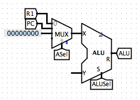
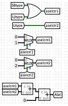
Note that since the method we use to generate ASel has the same intuition as how we generated ALUSel in Part 3.4.2.3.
5.2.2 Input of ALU [Input Y]
Then let's focus on the second input of ALU, which we denoted as Input Y. From the Datapath we can learn that, similarly, we have two options for Y, Reg[rs2] and Imm.
Imm: Immidiate, means specific number in RISC-V, opposite to variable
Again, we need to check out the Instruction sheet for intuitions to our selection controller for Input Y, which we call it BSel.
5.2.2.1 Intuitions for Input Y
We noticed that for Itype, SBtype, Utype, UJtype, and sw instructions, we all have operations with registers and immidiates. Thus, we know that when the instruction is one of the above types, we'll use Imm. We may assume that we just select R2 for the rest of instructions. However, we must also notice that there is a special intruction named swge which takes in no second input. This means that we should just pass in 0 for the second input. Thus, we develop a third option for Input Y. Now let's see what have we achieved for the ALU: 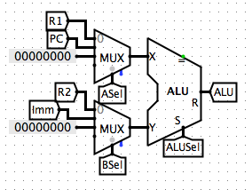
5.3 Imm
Now we almost finished the ALU part in our CPU. You may noticed that there's only one non-defined part in the ALU structure, the Imm.
The Imm depends on the type of the instructions. To get the correct Imm, we need to select the Imm based on the correct instruction.
5.3.1 Intuitions
The intuition here is that we generate different possible Imms for each type (Note that because of the type difference, we have different "grammars" reconstructing the Imm from the instruction).
You should be familiar with this part of information about RISC-V. If it confuses you, please check out HERE(Not-Published) for related information in RISC-V
Then, we may take usage of the same method we generated ALUSel in Part 3.4.2.3. (If the following parts confuses you, you may want to check it out)
5.3.2 Imm Re-Assembling
As what we discussed in Intuitions, we may need to first generate Imm for each possible types of instructions. This is just a simple re-assembling and sign-extending. So I'll just put my results here: 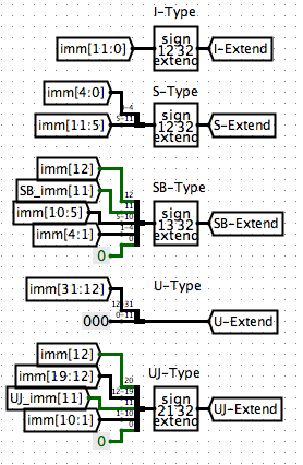
5.3.3 Indicator
Note: If you are confused about our implementations from this step, you may want to check out Part 3.4.2.3 for an thorough explanation to a similar method.
We use indicators to denote which instruction type we have: 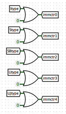
5.3.4 Counting
We count for the index of the types. This step transforms the index of types into bit-indexes. 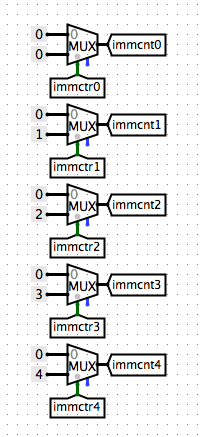
5.3.5 Accumulation
We accumulate the index values and get a controller ImmSel for our selection of Imm types of values. 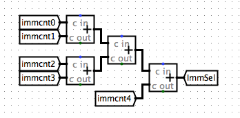
5.3.6 Get Imm
Now we have all possible Imms based on each instruction type and have an controller selecting the correct instruction type. We can build an Multiplexer to get our result. 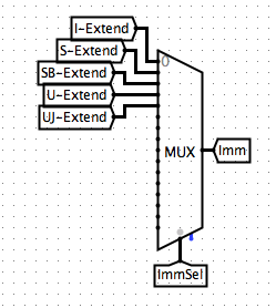
In Part 6 we'll be talking about Memory Management and Write Back systems.