Data Management in Registers - RegFile in CPU
4. Registers System Implementation
A processor register is a quickly accessible location available to a computer's Central Processing Unit (CPU)
Let's take an example to understand the usage of registers. Say if Bob wants to go out for work, and he has too many things to carry which he cannot take them all with him. However, Bob has some hand bags (registers)which he can carry some files with him. Each time before Bob goes out, he receives a message telling him the job today. So Bob goes out with his handbags for work. Say today, Bob's work is to add the number of files in his first handbag to that in the second bag and put the total number as a new file and store it into the second bag. Say if Bob's first bag carries a number 4 and his second handbag carries a number 2, after the operation, the number in his first bag would still be 4 but the number in his second hand bag would be 4+2=6. After all, Bob goes back home.
The second day, Bob receives a message saying that he is going to do some work with some new data. In order not to lose any data and do the work correctly, Bob receives an detailed instructions about how to do this. Firstly, Bob should find his cabinet at home (memory), and store the number in his first bag and second bag(for example) in the first level of the cabinet in sequence (say if each number takes 4 bits of place, and call the two numbers X and Y), and he uses his third handbag to store the address of the location of the storage in the cabinet. Then, he loads in two new data from certain places in the memory to the first and second handbag (say number A and number B), then he goes out and do the same work as last time and result in a new number C in his second handbag. He stores the number C in the given place in the memory. Then he needs to come back to continue his original work (the work that deal with number X and Y). Thus he went back to the cabinet, and find the location according to the address stored in his third handbag, and load the first 4 bits of memory to his first bag and next 4 bits into his second bag. Now, Bob successfully finished the extra work and came back to his original situation.
Here we may have some ideas about how registers work. Now let's look at how should we realize it's functionality.
4.1 Inputs & Outputs
4.1.1 Inputs
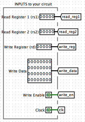
There are many inputs into the RegFile system. Firstly, we need to pass in the Read Register 1 (read_reg1), Read Register 2 (read_reg2) and Write Register (write_reg). Then, we have the Write Data (write_data) and signals Write Enable (write_en) and Clock (clk).
Note that here the register are more like a temporary data storage place rather than an input. We have the 8 registers (x1~x2, x5~x10, note that we do not use x0 since we need to keep it value 0)
We have the registers for implementation usages. read_reg1 and read_reg2 to indicate which two registers you want to read value from, and write_reg to indicate which register you want to write data to. The write_data shows the data you want to write into the registers. The write_en shows if we want to write the data from write_data to write_reg.
Here's how we show the registers and inputs: 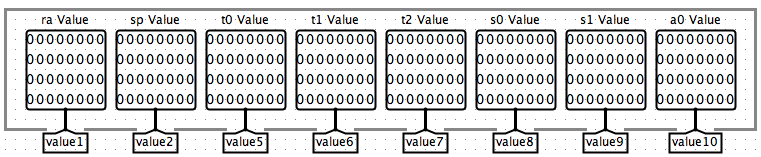
4.1.2 Outputs
The outputs are the read values from the given registers, after we write the data (if allowed by write_en) into write_reg. 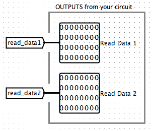
4.2 Intuitions
4.2.1 Pass Write Data to Inputs
The idea here is to first determine we want to pass in what data into which register. To do this, we first think of 8 different inputs corresponding to each register. And we can implement a Demultiplexer with a index write_reg and a signal write_en. Thus, if write_en is 1, data in write_data will be passed into the input number write_reg, and all other inputs will be None.
Note: This is very important the the value for other inputs are all None rather than 0. Or the other registers would all be cleared their values by 0 Note: Since we only have totally 9 registers here, we can extract the lower 4 bits of the
write_regand use a 4-bit Demultiplexer to save space.
The realization is as following: 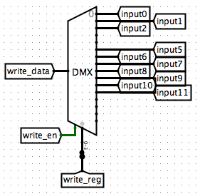
4.2.2 Pass Inputs into Registers
The next step is to pass the inputs into the registers. Note that although we don't change the value of register x0, I still showed it out for clarity. So we basically has 9 register with pass-in value as the corresponding inputs and the outputs as the value of the register, with a signal of clk. This explains why the other inputs were all None except for the assigned one. If the inputs has other values, the registers would all become that value and lose their original values.
The realization of this step is as following: 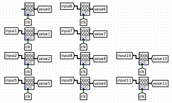
4.2.3 Read from Registers
Note that the output is the values we read from the registers. We have the inputs read_reg1 and read_reg2 indicating which registers we want to read data from. Thus we use two Multiplexers for reading from the two registers.
Since in the Demultiplexer part, we used a little trick which is splitting the
write_regand only extract the lower 4 bits to save space for the Demultiplexer, here I just keep the multiplexers the original presentation as a comparison.
Realization as following: 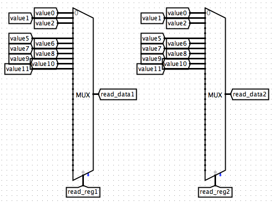
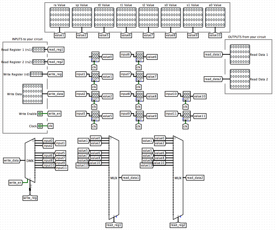
4.2.4 Overview
Now we've finished the designing for the RegFile. And here is an overview of the whole picture:
4.3 RegFile in CPU
Since we've discussed about the inputs/outputs about the RegFile, we can easily construct out RegFile in out CPU system. It should looks like: 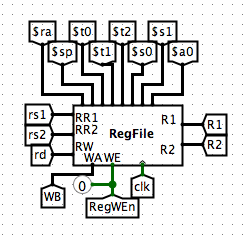
4.3.1 Input [WB]
There is one special thing that you may need to take a notice that the label for our write_data is WB. This means Write Back. It means the data passed by from the further operation results in the CPU. Since we know that the RegFile uses registers to achieve our data quick accessing storing and loading goals. The Write Back system makes sure that every time we read from the registers, we are getting the latest results and have no delays in data transmission which is highly likely to make system errors. To know more about the Write Back system, please check out Part 6.3
4.3.2 Controller [RegWEn]
RegWEn corresponds to the write_en in RegFile. When do we know if we want to write into the registers and when not? We need to check the instruction sheet for information. 
You may notice that when there's an Rtype, Itype, Utype, or UJtype instruction, we are writing data into the registers. Thus, we'll design the controller to make it fit this way. We'll simply use an or Gate. 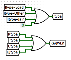
In Part 5 we will talk about the ALU designing.